[ad_1]
A relief well is a directionally drilled (https://www.drillingmanual.com/directional-drilling/” target=”_blank” rel=”noreferrer noopener”>Directional Drilling) offset wellbore whose purpose is to intersect a well that has https://www.drillingmanual.com/iwcf-well-control-from-to-z-principles/” target=”_blank” rel=”noreferrer noopener”>well control blowing out, thus enabling the control of the blowout.
Relief Well Plan
The relief well plan shall contain, as a minimum:
- The killing requirements limit rate and killing rate simulation study describes the primary kill method, including the number of relief wells required.
- Environmental risk assessment, including shallow gas assessment, seasonal constraints for relief well drilling, prediction of plumes, spill heat radiation, and noise profiles applicable to onshore or offshore operations.
- Have a minimum of two suitable drilling rig locations for two relief wells. If simulations show the need for two relief wells, then a minimum of three relief well locations should be in place.
- Directional relief well plans, including position uncertainty analysis of both target well and relief well(s).
- Relief well drilling equipment and services available for onshore or offshore operations via call-off drilling contract.
- Overview of the suitable drilling rig types for the relief well.
Relief Well Kill Requirement Limit Rate Modelling
A relief well plan aims to deliver high-density kill fluid at high rates into the target well after the intersection between the relief well and the blowout. This section explains the boundary conditions to simulate the relief well kill requirements limit rate and the subsequent steps to model the minimum required to kill rates to plan a feasible kill procedure (Driller’s Method – Wait & Weight Method).
After performing relief well kill requirements limit rate modeling and determining the kill rate for a specific relief well, the local well engineering team should be able to specify the following:
- Selected kill procedure, including (also check: https://www.drillingmanual.com/kill-sheet-calculators-spreadsheet-calculations-steps/” target=”_blank” rel=”noreferrer noopener”>kill sheet calculations):
- Kill fluid type during each stage
- The killing fluid weight during each stage
- Kill pumping rates during each stage
- Maximum pump pressures at the surface during each stage
- Hydraulic pump power requirement during each stage
- Total kill fluid volume needed for each kill fluid type/weight
- Feasibility of this scenario, including sensitivity to variations in downhole conditions.
Performing a relief well kill requirements limit rate and kill rate simulation study shall be with the assistance of the expectation case subsurface scenario that we already used in the casing design of the target well:
- Do not take into consideration reservoir depletion.
- In the case of an existing well, we will use the most recent known reservoir conditions to estimate the kill requirements.
Minimum Required Input Data for the Target Well
- Pore Pressure (PP) and Fracture Pressure Data
- Target Well Geometrical Data: the well trajectory as well as diameters of the flow conduit through the casings and tubing selected for the target well
- Reservoir Properties: Gas density, gas-to-oil ratio (GOR), crude density, condensate-to-gas ratio (CGR), condensate density, pollutant/toxin (H2S, CO2, and N2) contents, reservoir pressure/temperature and single (lumped) Productivity Index (PI)
- Outflow Data: collect the following data for estimation of the expected outflow condition
- Surface blowout: Ambient pressure and temperature at the wellhead location
- Subsea blowout: Temperature and pressure in the sea at the seafloor
Blowout Well Diagnostics
Below are the steps to perform blowout diagnostics with the blowout contingency planning tool:
- First, use the most recent/accurate data (production, reservoir).
- Second, run the blowout contingency planning tool to determine the kill rate and pump horsepower requirements and check the consistency of the relief well kill requirements limit rate with the figure provided by Reservoir Engineer.
Relief Well Data
A simplistic but feasible relief well plan should be sufficient for the order of magnitude estimation of kill requirements, such as kill fluid weight, kill rate, total volume, and pump hydraulic power. “Simplistic but feasible” refers to a simple trajectory while honoring geological constraints (i.e., strata where there is cementing for the casings/liners ). In addition, consider potential exclusion zones if they significantly increase the flow path length through the relief well (e.g., through an extended deviated or a horizontal section of the relief well).
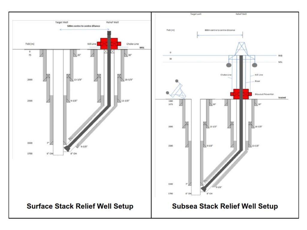
Figure 1 shows a typical intersection and highlights the practice of pumping kill fluid through the annulus via kill/choke line(s).
Pump/Kill/Choke Lines
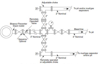
The diameter and length of these conduits shall be determined to yield realistic pump power requirements:
- Check the acceptable flow velocities to mitigate erosion of well components.
- For land operations, the minimum side outlet of a BOP spool should be at least 4 in (10.16 cm), with the position of this spool in the BOP based on risk assessing the possibility of losing the integrity of the surface lines/spool itself.
Kill Fluids
Determining Kill fluid(s) shall be by their density and viscosity. The density of the static kill fluid weight should not exceed the fracture gradient of any open formation (e.g., the formation at the intersection depth while pumping the kill fluid at recommended pump rate).
It would help to consider the above scenarios to generate the optimal solution and minimize operational hazards and risks while aiming for the lowest feasible kill rate. The local well engineering team should also consider developing a kill strategy after killing the target (e.g., if a considerable risk exists for losses in depleted zones or off-bottom kills).
Intersection Depth
Considering the following scenarios are necessary to select an initial optimum intersection depth for kill rate modeling:
For new wells:
- At the intersection point at the deepest casing shoe (Casing Setting depth)
- If needed, at a shallower intersection depth to enhance ranging and homing-in capabilities.
For existing wells:
- At perforations
- Above the production packer – requiring perforation or milling (milling in drilling)
- Off-bottom kills (below intermediate casing) requiring perforating or milling
Consider the following formation factors :
- Formation rock strength around the deepest casing with sufficient rock strength to avoid any losses during the blowout well kill
- Acid solubility in carbonates formations to achieve communication
- The thickness of the https://en.wikipedia.org/wiki/Caprock” target=”_blank” rel=”noreferrer noopener”>cap rock above the reservoir
Notes
NOTE: Plan for an OH section of the intercept well that is one size larger than the target wellbore to increase the probability. Drilling from the last casing should be done with the smallest OD drill string and bottom-hole assembly (BHA) components, as can be accommodated without negatively affecting the reliability of precise directional control. Minimize the drill collar length by adding additional heavyweight drill pipe in the drill string.
The drilling engineers should consider planning for setting an additional contingency liner (https://www.drillingmanual.com/casing-liner-hanger-systems-assembly-in-oil-gas/” target=”_blank” rel=”noreferrer noopener”>liner hanger system) between the last casing shoe before the interception. At the same time, if this is not feasible, the local well engineering team should consider upscaling the well plan with one casing size.
Spud Location:
One may ask what the distance should be between the blowout and the relief well. Before the previously discussed technology, the position of the relief well relative to the blowout was only a poorly educated guess. Consequently, No one was guaranteeing successful relief well operations. The normal plan was to drill into the zone produced in the blowout, manifold all pumps we could gather, and pump like hell. Sometimes it worked, and sometimes, it did not.
Generally, the departure of the relief well from blowout is a function of overall project management; however, the closer, the better.
Below is the recommended departure for such wells:
- Surface wellheads: 1,500 ft (457 m) lateral distance at the surface between the blowout well and relief well in upwind direction relative to the blowout well.
- Subsea wellheads: 2,500 ft (762 m) lateral distance at seabed between blowout and relief well in upwind and up-current direction relative to the blowout well.
Directional Relief Well Planning
Drilling engineers shall be able to specify a directional relief well plan that should contain, as a minimum:
- Primary spud location(s) for the required number of wells plus one additional backup spud location
- Relief well trajectory
- The time estimate for drilling relief wells
Spud Location Data Review
We should consider the following factors when identifying a suitable spud location:
- Historical information about the field, location of discovery, and appraisal wells
- Seabed survey data or topographical maps showing the suitability for a spud location
- Absence of pipelines, power and communication cables, roads, buildings, water sources, or any other objects underneath or close to the spud location
- The absence of geo-hazards, shallow gas, shallow formation dipping planes, faults, or any other shallow hazards
- Safe area to spud and safe mooring locations available
- Access roads
- Access to surface water
- Environmental requirements.
Choose an alternative spud location if the above data yields insurmountable constraints. After selecting a primary and secondary spud location, set up the directional planning database.
The optimal kill fluid schedule is also determined by the availability of the required fluids and the predicted downhole pressure development during and after the kill, for example:
- When water is in short supply (desert), it may be best to aim for the final kill fluid weight in a single-stage kill.
- Where the kill fluid required is only available in limited volumes, a two-stage dynamic kill consisting of a lightweight kill fluid stage followed by a stage-static kill-weight fluid.
- If local depletion effects are significant, it may be necessary to kill the well with lighter fluid and displace this fluid with heavier fluid in several stages as the near-wellbore reservoir pressure recharges.
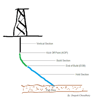
Relief Well Trajectory
We have previously discussed the relief well spud location. For the target, it shall intersect depth at the deepest casing shoe, assuming the setting of the shoe will be near the base of the caprock.
We shall consider the following while planning a relief well:
- By-passes the target well at least 900 ft (300 m) before the intersection point.
- The combined position uncertainty of both the target well and the relief well is less than 45 ft (15 m) at the bypass depth.
- Also, It should have a minimum distance of 90 ft (30 m) between the edge of the relief well’s uncertainty ellipsoid and any neighboring well’s uncertainty ellipsoid at the bypass depth.
- To incline less than 60°.
- In addition, it shall have an incidence angle between the relief well and target well of more than 2° and less than 8°.
- Kick-off depth that is common for the area
- Build-up and drop-off rate less than recommended 3°/100 ft (30.48 m)
- Geologic conditions assessment from spud to intersection (the ability for doglegs >3°/100 ft (30.48 m) if required, gas charging, drilling and geologic hazards, faults).
- It is better to keep all relief well casing shoe-setting depths the same as the target well shoe depths, except for the deepest casing shoe depth (you may set CSG. shallower to allow for the contingency liner).
Relief Well Time Estimate
It would help if we prepared a time estimate for the time between the actual blowout occurrence and the final well kill. As a general rule of thumb, the relief well construction takes the same amount of time as the target well; however, take into account the extra time due to the following:
- Construction of a relief well site and https://www.drillingmanual.com/oil-rig-move-operations-procedure-onshore-offshore/” target=”_blank” rel=”noreferrer noopener”>rig mobilization per local requirements (e.g., piling for rig) and availability of resources (civil construction) may represent a considerable time on the critical path.
- After the last casing, the time plan should consider drilling the remaining section with a https://www.drillingmanual.com/downhole-drilling-mud-motors-components-diagram/” target=”_blank” rel=”noreferrer noopener”>mud motor. To maintain directional control, we should assume that drilling with 50–75% sliding will occur, resulting in an additional drilling time of 50% over rotary drilling.
- When ranging starts, for each ranging run, the https://www.drillingmanual.com/api-drill-pipes-specifications/” target=”_blank” rel=”noreferrer noopener”>drill pipe needs to be POOH, a ranging run on wireline performed, and the drill pipe run-in-hole (RIH) (https://www.drillingmanual.com/tripping-pipe-procedures-operations-rig-safety/” target=”_blank” rel=”noreferrer noopener”>pipe tripping) again to resume drilling. A ranging run on wireline takes roughly four hours to RIH, collect ranging data, and pull-out-of-hole (POOH).
- Also, when approaching a bypass, perform a ranging run every 150 ft (50 m), with some three additional ranging runs to potentially orient the bit prior to intercepting. Hence, perform over a distance of 900 ft (300 m), a minimum of 6–9 ranging runs.
- If there is a contingency, we plan to run a liner and include the time in the estimate.
Rig Requirement And Equipment
The drilling engineer should be able to:
- Specify a time estimate for mobilization of the minimum required several rigs with similar or higher specifications than the rig that drilled the well to be intersected, clearly reflecting this time in the overall time estimate for drilling the relief well and dynamically killing the blowout.
- Call-off blowout services from third-party companies and obtain blowout engineering and relief well drilling support.
Kill Equipment Considerations
Dynamic kill operations usually involve extremely high density [<18.9 ppg (2.2 SG)] fluid delivery rates and large volumes of high-density kill fluids. The significant hurdles involved with implementing such an operation include the following:
- Obtaining the required mud pump capacity – pressure and rate with adequate redundancy
- Sufficient fluid storage
- Maintaining the kill fluid for an extended period.
- High-rate transfer of kill fluid to the high-pressure pumping system
Therefore, the primary components of the killing equipment should be:
- Pumping equipment on:
- Rigs
- Stimulation vessels/trucks
- Supply vessels/trucks
- Fluid storage, maintenance, and transfer
- Surface pump lines, valves, and ancillary equipment
Well Spot Software in Relief Wells
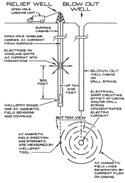
Well spot is an electromagnetic ranging or proximity measuring service supplied by Halliburton/Vector Magnetics. The well spot measures distance and direction from positions along a borehole to the steel casing or drill string in a second borehole. The https://www.drillingmanual.com/directional-driller/” target=”_blank” rel=”noreferrer noopener”>directional driller uses this information to adjust the trajectory of the relief well at frequent intervals during drilling to achieve the desired proximity or intersection with the target well. The precision of the measurement, teamed with a https://www.drillingmanual.com/steerable-downhole-drilling-mud-motor-systems/” target=”_blank” rel=”noreferrer noopener”>steerable drilling system, is adequate to achieve borehole intersection. Higher Wellspot measurement and steering correction frequency can control the geometry of the intersection sufficiently to allow OH re-entry below a fish (https://www.drillingmanual.com/fishing-in-drilling-oil-gas-operations-full-guide/” target=”_blank” rel=”noreferrer noopener”>fishing operations in drilling) or milling of a window and casing re-entry from the outside (https://www.drillingmanual.com/sidetracking-well-drilling-time/” target=”_blank” rel=”noreferrer noopener”>Sidetracking).
Relief Well drilling Operations Sequence Example
A blowout at a deep, high-pressure well in the North Sea is a good example.
- Prepare a wellbore schematic (https://www.drillingmanual.com/free-wellbore-schematic-excel-template/” target=”_blank” rel=”noreferrer noopener”>Free Wellbore Schematic Excel Template).
- Determine the approximate bottom hole location and preferential direction of the drift.
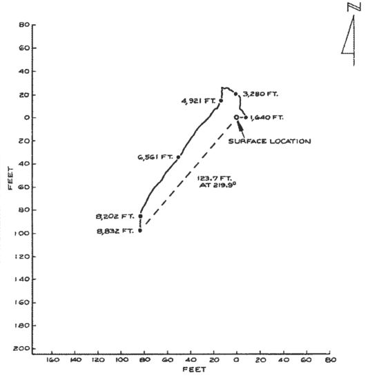
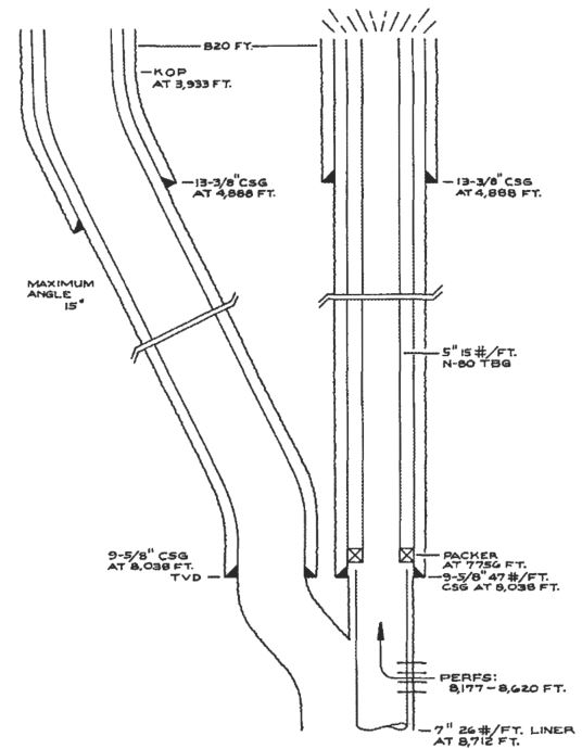
- Select and build a location for the relief well approximately 820 feet northeast of the blowout.
- Drill a 17 1/2 inch hole to 3933 feet true vertical depth and reduce hole size to 12 1/4″ inches for directional work.
- Pick up the motor, 1 1/2 degree https://www.drillingmanual.com/bent-sub-mud-motor-directional-drilling/” target=”_blank” rel=”noreferrer noopener”>bent sub with motor, and https://www.drillingmanual.com/measurement-while-drilling-mwd-tool-oil-gas/” target=”_blank” rel=”noreferrer noopener”>MWD, and build the angle to 15 degrees at approximately 1.5 degrees per 100 feet.
- Lay down the motor, bent sub, and MWD, and pick up the holding assembly.
- Drill to intermediate casing point at 4888 feet true vertical depth, holding angle at 15 degrees.
- Open a 12 1/4 inch hole to 17 1/2 inches.
- Set and cement 13 3/8 inch casing. If kill considerations permit, reduce the hole size to 12 1/4 inches and the casing size to 9 5/8 inches.
- Hold 15 degrees in the 12 1/4 inch hole to 6561 feet measured depth.
- Run wellbore proximity log to detect blowout wellbore.
- Make course corrections as the wellbore proximity log requires using a motor, bent sub, and MWD.
- Drill to 7090 feet measured depth and run wellbore proximity log.
- Make course corrections as the wellbore proximity log requires using a motor, bent sub, and MWD.
- Using a https://www.drillingmanual.com/types-of-bottom-hole-assembly/” target=”_blank” rel=”noreferrer noopener”>pendulum bottom hole assembly, drop the angle to vertical. Run the wellbore proximity log at 200-foot intervals until confirmation of blowout wellbore.
- Intercept the casing in the blowout well at 8000 feet true vertical depth.
- Drill to casing point at 8038 feet true vertical depth and run the wellbore proximity log.
- Run 9 5/8 inch casing to 8038 feet true vertical depth. If kill considerations permit, reduce the hole size to 8 1/2 inches and the casing size to 7 inches. ( Run CBL or CBL/VDL to ensure that the cement is in good condition)
- Drill out with 8 1/2 inch (or 6-inch) drilling bits and run a wellbore proximity log as required to intercept the blowout wellbore.
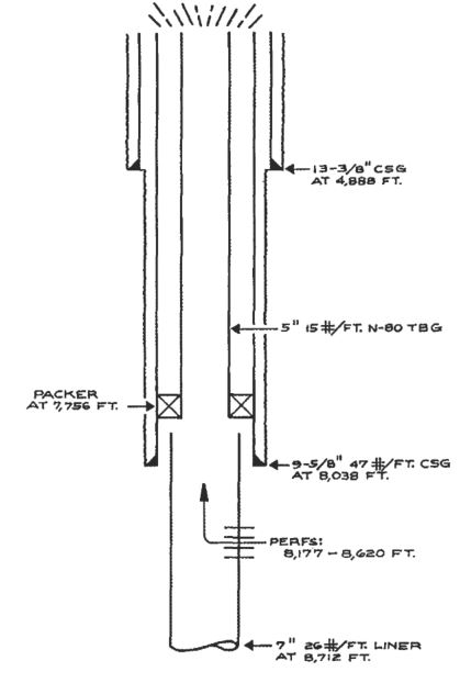
- Then drill into the blowout wellbore (see figure 10).
- Kill the blowout according to the plan and procedure.
https://www.drillingmanual.com/relief-well/”>